
|
AIM_HOST allows quick and easy automatic calibration of the AIM unit with the use of a special Calibration Box Standard that contains a precise, standard impedance network. The calibration box typically comes with both the "Basic" and "Complete" AIM Package. Calibration is achieved by connecting the AIM's impedance electrodes to the Calibration Box, and then clicking on the [Calibrate AIM ] button on AIMHOST 's Main Communication Screen. This, in turn, sends appropriate control codes to the AIM to place it in the Calibration Mode and to start the actual calibration process. All of the calibration operations (baseline setup, calibration-value network switching, calibration process sequencing, etc.) are automatically handled by the AIM device once it receives the proper control codes from the AIMHOST system. AIM_HOST then displays the calibration results, and gives the user the options to either save the calibration data as the AIM's default calibration values, or to abort and ignore the most recent calibration. (Note: The calibration should take only a couple of seconds.) The AIM Calibration Box and How to Use It The AIM Calibration Box contains a special passive electronic impedance network used by the AIM as a calibration "Standard" to simulate connection of the electrode cable to a subject. When calibrating the AIM unit, the AIM's four impedance-cable electrodes (#1, #2, #3, #4, and #5) are connected to the four corresponding electrode terminals (labeled 1, 2, 3, and 4) on the Calibration Box. NOTE: Electrode lead #5 should also be connected to terminal #1 on the calibration box before calibrating the AIM. Having the calibration network external to the AIM device, and connected via the impedance electrodes, permits some of the calibration process to be performed through the AIM's electrodes. This, in turn, serves the purpose of also checking the electrode assembly during the calibration process. The diagram below shows how the AIM electrode cable connects to the calibration box: 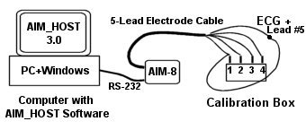 Starting the Calibrating Process Start the AIM calibration process by clicking on the [Calibrate AIM] button on the AIMHOST Main Control Screen. This button is active only when the AIM is in the Command Mode! The AIM's Calibration Process As mentioned above, all of the calibration operations (baseline and calibration-value network switching, and calibration process sequencing) are handled automatically by the AIM-8 after receiving the proper control codes from the AIMHOST system. When the [Calibrate AIM] button is clicked, the AIM-8 powers up the impedance cardiograph portion of the monitor, and puts it into the Calibration Mode. It then prompts the user to connect the four impedance electrodes (#1, #2, #3, and #4) to the AIM Calibration Standard Box. Please NOTE: You should also connect lead #5 (the +EKG lead) to terminal #1 on the calibration box along with electrode lead #1. This will insure the EKG baseline value will be determined correctly by the AIM monitor during the calibration process, resulting in an EKG signal that tracks a correct baseline. At this point, you are given the choice of either continuing with the calibration or aborting the calibration process. You must respond by either pressing the [Space Bar] key to proceed with the calibration, or the [Enter Key] to abort the calibration process. NOTE: For the calibration process to be successful, the four AIM Electrodes (1, 2, 3, and 4) MUST be connected to the Calibration Box before continuing! And don't forget, it is also a good idea to have electrode #5 (+EKG) connected to terminal #1 on the calibration box as well! When the [Space Bar] is pressed, the AIM will switch it's input network to Zero-Baseline conditions, and proceed to obtain calibration information for these conditions for approximately 1 second. Then, the AIM switches it's impedance cardiograph network to some known signal values (i.e. dZ/dt = 1 Ohm/sec, Zo = 25.5 Ohms, ECG R-Wave peak = 1 mV, etc.) generated by it's internal calibration circuitry and the external Calibration Box, and then acquires approximately 2 seconds of these calibration signals. Following this process, the AIM uses this calibration information to compute "Baseline-Offset" values and parameter "Scale- Factors" for each of the impedance cardiography signals. The AIM Calibration Results Once the acquisition of calibration data has been completed by the AIM, which takes about 2 seconds, the baseline offset and calibration scale factors for the dZ/dt, Zo, and ECG signals are computed. The true system Zero-Baseline Reference and dZ/dt Peak (1 Ohm/sec.) ADC values are also determined. Following this, the calibration results are transmitted back to the AIMHOST system and displayed on the "AIM Interactive Display Screen" for the user to view. At this point, you are given the opportunity to either SAVE the calibration results (Scale Factor & Baseline Values) in the AIM's non-volatile memory, or to ABORT saving the calibration and return to the AIM's Command Mode. Saving the Calibration Data The user can save the calibration results (Scale Factor & Baseline Values) in the AIM's non-volatile memory by responding to the AIM's "calibration results prompt." This simply involves pressing the [S] Key on the AIMHOST system's keyboard. The New calibration data will be immediately stored in the AIM's EEPROM solid-state memory. The AIM device will use the calibration information each time it is powered-up (connecting it to a 9-Volt battery or a 9-Volt power supply). Return to top of page Back to Applications Information Page |